A Bleed Ball Valve isolates pressure and releases trapped fluid from a pipeline or equipment cavity. Its compact body usually contains a drilled ball, sealing seats, and a small bleed port. Turn the handle 90 degrees, and the main passage closes. The bleed port can then confirm whether pressure remains.
This detail matters in oil, gas, chemical, and industrial process systems. A sealed section may still hold pressure after the main valve closes. That pressure can appear as a thin spray, a hiss, or a sudden gauge movement. Small signs. Serious consequences. Proper venting and verification remain essential.
Grand View Research valued the global industrial valves market at approximately USD 78.8 billion in 2023. It projects continued growth through 2030, driven by energy, water, and process infrastructure. MarketsandMarkets also reports sustained demand for industrial valves, while noting that safety, automation, and maintenance efficiency influence purchasing decisions. These reports describe the wider valve market, not Bleed Ball Valve sales alone. That distinction is easy to miss.
Valve engineer Richard W. Greene offers a practical reminder: “A valve must be selected for the service, not merely for the pipe size.” His point applies directly here. Material compatibility, pressure rating, temperature, seat design, and drainage direction all affect performance. A stainless-steel body may suit corrosive service, but its seals might not. The valve can look right and still be wrong.
This guide explains how a Bleed Ball Valve works, where it fits, and what inspection details deserve attention. It also questions a common assumption: closing the main valve does not always prove zero pressure.
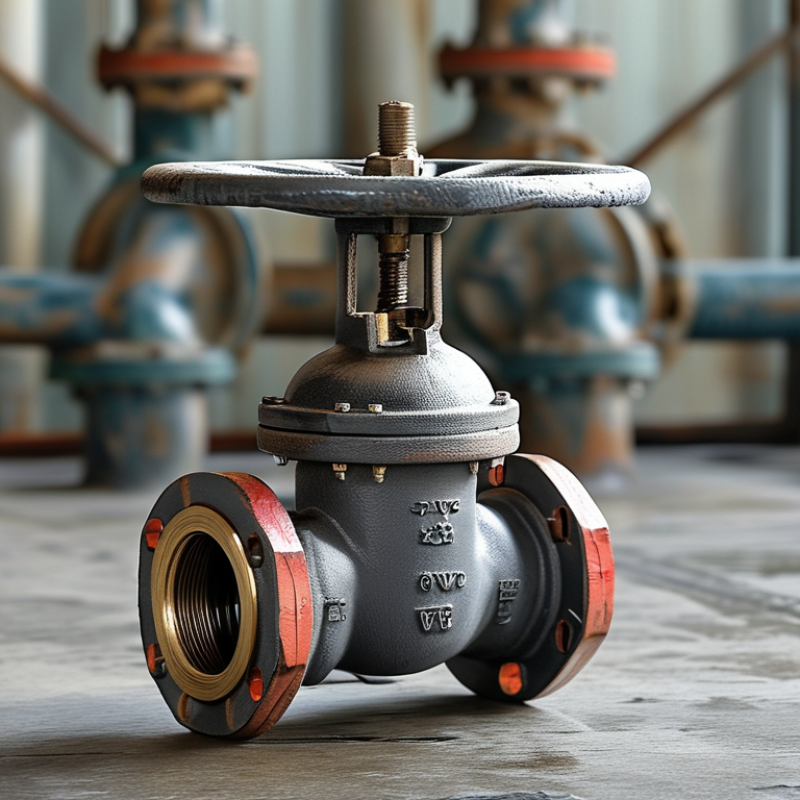
A bleed ball valve is a compact isolation device with a rotating ball and a small bleed port. Its basic purpose is to stop fluid flow and release trapped pressure from an isolated section. The ball contains a drilled passage. When the handle turns 90 degrees, the passage aligns with the pipeline and allows flow. When closed, the solid side blocks the passage.
After isolation, the bleed port can discharge remaining liquid or gas into a controlled collection point. This helps technicians verify that pressure has fallen before maintenance begins. However, a bleed port does not replace proper isolation procedures. Valve performance depends on pressure rating, temperature limits, seal condition, and correct installation. Field checks often reveal a simple problem: the main valve is closed, but trapped pressure remains. That detail is easy to underestimate.
Tips: Confirm the valve’s flow direction and rated service before installation. Open the bleed connection slowly, while wearing suitable protective equipment. Check for leakage around the stem and body. Keep the discharge path controlled. A pressure gauge can provide useful evidence, but it may not respond immediately. Designs vary, and the wrong assumption can create risk. Inspect the valve regularly, especially after repeated cycling or exposure to corrosive media.
A bleed ball valve combines flow isolation with controlled pressure release. Its main body contains a drilled ball, two sealing seats, a stem, and a handle or actuator. The stem connects to the ball through a small drive slot. When the stem turns 90 degrees, the ball moves from an open passage to a solid barrier.
The valve seats press against the ball and limit leakage around the flow path. In a floating design, line pressure helps push the ball toward the downstream seat. Larger valves may use a trunnion-mounted ball, supported by upper and lower bearings. This structure reduces operating torque and improves stability under pressure. The body also includes a cavity between the ball and seats. That space is important.
A separate bleed port connects to the trapped cavity. With the main valve closed, an operator opens the bleed passage gradually and checks for remaining pressure or liquid. This step can confirm isolation before maintenance, but it is not proof of zero energy by itself. Pressure may enter the cavity through seat damage, thermal expansion, or an incorrect operating sequence. A small vent opening can also produce a sharp release. I have found that internal diagrams often look cleaner than real service conditions. Dirt, worn seats, and tight stem packing can change valve behavior. For reliable inspection, technicians should verify the valve position, observe the bleed outlet, and use suitable pressure instruments. Locating the bleed port on the side or bottom also affects drainage and access.
| Component or Feature | Internal Structure | How It Works | Typical Function or Consideration |
|---|---|---|---|
| Valve Body | Pressure-containing outer shell with an internal flow passage and one or more body joints. | Contains the ball, seats, stem, and cavity while resisting the system pressure. | Common body configurations include one-piece, two-piece, and three-piece designs. Construction material must match the fluid, pressure, temperature, and corrosion conditions. |
| Ball | Spherical rotating closure member with a drilled port aligned through its center. | A quarter-turn rotation normally changes the valve from open to closed. The bore aligns with the pipeline when open and turns across the passage when closed. | Full-bore balls can reduce pressure loss and facilitate pipeline pigging. Reduced-bore designs may be more compact or economical. |
| Ball Seats | Sealing rings positioned on the upstream and downstream sides of the ball. | Seat contact creates the primary seal around the ball when the valve is closed. | Seats may be soft, such as polymeric materials, or metal-seated for higher-temperature, abrasive, or severe-service applications. The allowable temperature and chemical compatibility are design-dependent. |
| Valve Stem | Rotating shaft connected to the ball and extending through the valve body. | Transfers torque from a hand lever, gearbox, or actuator to rotate the ball. | Many industrial designs use an anti-blowout stem feature so that internal pressure cannot eject the stem if the stem-retaining hardware is damaged. |
| Stem Packing and Seals | Packing rings, O-rings, or other sealing elements located around the stem and body joints. | Limit external leakage where the moving stem passes through the pressure boundary. | Seal material selection depends on temperature, pressure, fluid chemistry, emissions requirements, and operating frequency. |
| Internal Valve Cavity | Enclosed space between the ball, seats, and body wall when the valve is closed. | May contain trapped process fluid after both seats are closed. The cavity pressure can be checked or relieved through the bleed connection. | Cavity relief requirements depend on the service and design. Thermal expansion of trapped liquid can create a significant pressure increase. |
| Bleed Port or Bleed Valve | A small outlet connected to the valve cavity, usually fitted with a separate isolation valve, plug, or test connection. | When opened under controlled conditions, it releases, drains, samples, or measures fluid from the isolated cavity. | The bleed connection is not automatically a substitute for a certified pressure-relief device. Discharge must be routed and managed safely. |
| Double-Block-and-Bleed Arrangement | Two independent sealing interfaces isolate the process from a central cavity, which is connected to the bleed outlet. | Both seats are closed, and the cavity is then bled or monitored to verify isolation and detect seat leakage. | This arrangement supports maintenance, pressure testing, draining, venting, and leakage verification without removing the valve from the line. |
| Open Position | The ball bore is aligned with the inlet and outlet passages; the seats contact the ball around the flow path. | Fluid flows through the aligned bore with relatively low resistance compared with many throttling valve designs. | A standard ball valve is primarily intended for isolation, not continuous throttling, unless the design is specifically rated for control service. |
| Closed Position | The ball is rotated approximately 90 degrees so its solid surface faces the flow passage. | The seats press against the ball and block the main pipeline flow. The cavity can remain filled unless it is vented or drained. | The actual shutoff performance depends on seat condition, differential pressure, fluid properties, temperature, and the applicable test standard. |
| Bleeding Sequence | The main ball is closed, the bleed outlet is connected to a suitable drain, vent, recovery, or monitoring system, and the outlet valve is opened gradually. | Trapped pressure or fluid leaves the cavity. A pressure gauge or controlled discharge can indicate whether either seat is passing. | Operators must confirm the discharge destination, fluid hazards, pressure rating, and site procedures before opening the bleed connection. |
| Pressure and Temperature Rating | The rating is determined by the body, seats, stem seals, end connections, and applicable design standard. | The valve remains within its safe operating envelope only when pressure and temperature are kept below the specified limits. | No single pressure or temperature value applies to every bleed ball valve. The nameplate, technical specification, and installation requirements must be checked. |
| Common Applications | Installed in process, pipeline, storage, and equipment isolation systems where cavity access is useful. | Provides shutoff plus a means to drain, vent, sample, test, or confirm isolation between the valve seats. | Typical services include hydrocarbon, natural gas, chemical, water, and other industrial fluids, subject to material compatibility and safety requirements. |
A bleed ball valve combines isolation and controlled pressure release in one compact assembly. Its ball has a drilled passage that turns flow on or off. When closed, the valve blocks the process line. The bleed port then releases trapped pressure from the cavity between sealing surfaces.
Pressure control happens in stages. An operator closes the main valve and checks the downstream gauge. The bleed port opens slowly toward a safe recovery or vent system. If the gauge does not fall, the primary seal may be leaking. That warning matters.
A bleed ball valve does not reduce upstream pressure; it only isolates and relieves trapped pressure. API 6D guidance supports functional testing and documented inspection for pipeline isolation equipment. In field work, technicians should verify zero pressure before removing fittings.
The NACE IMPACT study estimated global corrosion costs at 2.5 trillion dollars, equal to about 3.4% of worldwide economic output. Corrosion can damage the bleed port, stem, or sealing surfaces, making pressure release unreliable. IOGP’s 2023 safety performance reporting also treats loss of containment as a key process-safety concern.
A clean, visible gauge helps, but it is not enough. Temperature changes can rebuild cavity pressure after bleeding. That detail is easy to miss. Regular testing, correct materials, and a clearly directed discharge path improve reliability. Still, field conditions are imperfect, and every valve deserves a second pressure check.
A bleed ball valve combines isolation with controlled pressure release. Its main ball blocks the process line. A smaller bleed port then vents trapped fluid from the isolated section. Operators can confirm pressure has fallen before removing instruments or opening equipment. This simple sequence reduces exposure to stored pressure, but it does not replace site procedures or verification.
Common configurations include a single isolation valve with an integral bleed, a double block and bleed assembly, and a compact valve manifold. Floating-ball designs suit many moderate-pressure services. Trunnion-mounted designs can support larger sizes and higher loads. You may find these valves on pipeline sampling points, pressure transmitters, filter housings, tank farms, and process skids. They are useful where space is limited and maintenance access matters.
The fluid, temperature, pressure rating, seal material, and discharge route must match the application. Small details matter.
Tips: Close the main valve slowly. Bleed to a safe collection point. Check the gauge, then verify zero pressure independently. Never assume a silent line is empty. In field work, selection is not always tidy; a compact assembly may save space but complicate inspection. I have seen unclear port markings cause hesitation during maintenance. Clear labels and a practical operating sequence are worth the extra attention.
What Is a Bleed Ball Valve and How Does It Work?
A bleed ball valve isolates a section of piping and releases trapped pressure through a separate port. Its internal ball turns with the handle, opening or closing the main flow path. The bleed port helps technicians confirm isolation before removing instruments or fittings. However, it is not automatically a pressure-relief device.
Installation requires careful planning. Check the valve’s pressure, temperature, material, and connection type against the system requirements. Shut down the line, isolate all energy sources, and verify zero pressure with a suitable gauge. Open the bleed path slowly and direct any fluid into a safe collection system. Never point the outlet toward people, electrical equipment, or an unprotected work area. Use correct thread sealant and avoid excessive tightening, which can damage connections.
Maintenance should include visual checks for corrosion, leakage, loose hardware, and damaged handles. Exercise the valve periodically, but only after confirming safe operating conditions. Inspect the bleed outlet for blockage; a blocked port can create false confidence during isolation. Replace worn seals with compatible parts, following approved procedures. A common mistake is testing only the handle position. Position alone proves little. Pressure verification matters. No checklist catches every mistake, so technicians should pause when readings, valve movement, or system behavior seems unusual.
: It isolates a piping section and releases trapped pressure through a separate bleed port. It is not automatically a pressure-relief device.
A stem turns the internal ball through 90 degrees. The drilled passage opens flow, while the solid side blocks it. The handle position gives a useful clue, not complete proof.
It connects to the cavity between the ball and sealing seats. With the main valve closed, technicians open this passage slowly. They can then observe pressure or liquid at the outlet.
No. Pressure may enter through damaged seats, thermal expansion, or incorrect sequencing. A blocked bleed port can also create false confidence. Use a suitable pressure instrument and follow the approved isolation procedure.
Confirm the valve’s pressure rating, temperature range, materials, and connection type. Match these details with the piping system. Check access to the side or bottom bleed outlet.
Open it gradually and direct discharge into a safe collection system. Keep the outlet away from people, electrical equipment, and unprotected areas. A small opening can release fluid sharply.
Inspect for corrosion, leakage, loose hardware, damaged handles, and blocked outlets. Exercise the valve only after confirming safe conditions. Replace worn seals with compatible parts and approved methods.
Larger valves may use a supported ball with upper and lower bearings. This design can reduce operating torque and improve stability under pressure. Actual service may still differ from diagrams.
Stop when readings, stem movement, or system behavior seems unusual. Dirt, worn seats, and tight packing can change valve response. A checklist helps, but it catches nothing perfectly.
A Bleed Ball Valve is a compact flow-control device designed to isolate a section of piping or instrumentation while safely releasing trapped pressure or fluid through a separate bleed outlet. Its main components typically include a valve body, ball with a precisely drilled passage, seats, stem, handle, seals, and a bleed port. When the ball rotates, it either aligns with the pipeline to allow flow or turns across it to stop flow. After isolation, the bleed passage can be opened to discharge residual pressure, helping operators confirm that the isolated section is safe to service.
Bleed Ball Valves are available in various connection styles, port designs, and single- or double-isolation configurations. They are commonly used in process lines, hydraulic systems, gas installations, testing equipment, and instrumentation assemblies. Proper installation requires correct flow orientation, compatible materials, secure connections, and adequate support. Regular inspection should focus on leakage, seal wear, corrosion, and handle operation. Before maintenance, the system must be shut down, depressurized, and verified through the bleed outlet, with appropriate protective equipment and safe operating procedures in place.

Shoulong Valve