In high-pressure process plants, isolation is not a paperwork exercise. It is a physical barrier between workers and stored energy, toxic fluids, or combustible gases. A Double Bleed Valve combines two shutoff barriers with a monitored bleed point. This arrangement can support safer maintenance, testing, and equipment changeovers.
The value becomes clearer at the worksite. An operator closes the upstream and downstream seats, then opens the central bleed connection. Any trapped pressure should discharge through a controlled route, while the bleed port helps confirm seat performance. API Specification 6D addresses pipeline and process isolation valve requirements, including double-block-and-bleed configurations. OSHA’s Control of Hazardous Energy standard, 29 CFR 1910.147, also stresses documented isolation, verification, and worker training. The valve supports these controls. It does not replace them.
Industry evidence reinforces this discipline. The International Association of Oil & Gas Producers reports that loss of containment and barrier failures remain important process-safety concerns in its annual performance reporting. CCPS guidance similarly links reliable isolation with stronger process-safety management and permit-to-work practices. Field experience shows small details matter: a blocked bleed line, incorrect valve position, or unverified gauge can undermine a carefully designed system. That gap matters. A Double Bleed Valve is not magic. It requires correct sizing, suitable materials, regular inspection, and independent verification. Engineers must also assess pressure, temperature, fluid toxicity, leakage class, and maintenance access before selection. When these factors align, double isolation with visible bleed control can provide a more credible safety layer than a single shutoff valve.
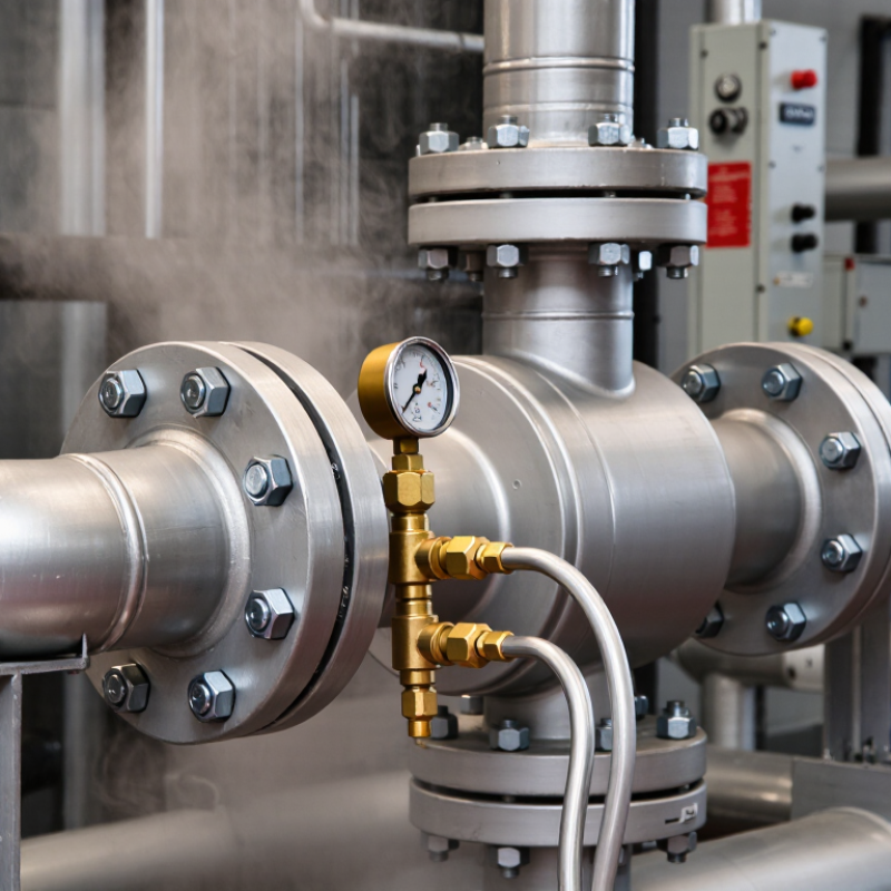
A double bleed valve combines two isolation valves with a bleed port between them. The two valves close against the process flow. The central port then releases trapped pressure into a controlled drain or collection system. This arrangement creates a visible verification point. Operators can check whether pressure remains between the closed valves. It is more informative than trusting one closed valve alone.
In field maintenance, this design helps isolate instruments, pumps, and process sections before inspection. A technician closes both valves, opens the bleed connection, and watches the pressure indicator. No pressure should remain between the barriers. If pressure returns, one isolation valve may be passing. That warning can prevent unexpected release during work. The method sounds simple, but rushed checks still create risk. Valve position, seal condition, and pressure rating all require attention.
Tips: Confirm the media, temperature, and pressure before selection. Use suitable hoses and containers for the bleed outlet. Keep the outlet pointed away from people. Follow site isolation procedures and verify zero energy before loosening fittings. A double bleed valve improves control, but it cannot replace competent training or regular inspection. Seals can age quietly. Reviewing the arrangement after installation is worthwhile.
A double bleed valve arrangement uses two isolation barriers with a controlled bleed point between them. This design creates a visible space for checking pressure, draining trapped fluid, or sampling leakage. If the downstream valve passes, the bleed point can reveal it before work begins. That extra evidence matters around hot oil, compressed gas, or corrosive liquid. Safety improves through verification, not assumption.
During maintenance, an operator closes both isolation valves and opens the bleed slowly. A local gauge should fall to zero, but zero pressure alone is not proof of safety. Temperature, blocked vents, and inaccurate instruments can mislead. The bleed outlet needs safe routing, clear labeling, and enough capacity for the expected fluid. Lockout procedures, valve ratings, and site standards still apply. The hardware supports isolation; it does not replace trained judgment.
Good practice includes testing the valves, recording leakage rates, and checking the cavity before loosening a flange. In field inspections, small errors often matter: a half-closed bleed, a hidden drain, or a damaged seat. It is not foolproof. Some systems need independent pressure relief or a second verification method. Engineers should review flow direction, pressure class, temperature, and failure modes before selection. Operators should rehearse the sequence under normal conditions. Real work is rarely perfect, and procedures deserve revision when the first attempt exposes confusion.
A practical comparison of single isolation and double isolation with bleed for pressurized fluid systems. Actual valve selection, pressure ratings, materials, and verification methods must be confirmed against the applicable design code and operating conditions.
| Safety Dimension | Single Isolation | Double Isolation and Bleed | Safety Benefit | Verification or Design Note |
|---|---|---|---|---|
| Isolation barriers | Provides one primary barrier between the live system and the isolated section. | Provides two independent shut-off barriers with a bleed or vent connection between them. | Adds barrier redundancy and reduces dependence on a single sealing element. | Both isolation elements should be suitable for the service and rated for the design pressure and temperature. |
| Trapped pressure control | Pressure may remain trapped downstream of the closed valve if no dedicated depressurization point is available. | The intermediate cavity can be connected to a controlled bleed, drain, vent, or pressure-monitoring device. | Allows trapped pressure to be released or managed before maintenance activities. | Bleed discharge should be routed to a safe location or closed recovery system. |
| Leakage detection | Seat leakage can be difficult to distinguish from pressure changes in the isolated section. | Leakage from either isolation element can be observed through pressure build-up or flow at the bleed point. | Provides an additional method for confirming barrier performance. | Detection sensitivity depends on the bleed arrangement, instrumentation, fluid properties, and test procedure. |
| Maintenance exposure | Maintenance personnel may rely on one valve to prevent hazardous fluid migration. | The second closed valve remains available if the first barrier experiences seat leakage, subject to correct operation. | Reduces the likelihood of fluid reaching the work area during isolation. | Double isolation and bleed is not automatically equivalent to positive isolation for every intrusive task. |
| Pressure equalization | Pressure differences may remain across the isolation valve, which can increase operating loads or complicate opening. | The bleed path can be used to monitor or control pressure in the space between the barriers. | Improves control of differential pressure during isolation and restoration. | Equalization procedures must account for stored energy, fluid hazards, and the permitted operating sequence. |
| Failure tolerance | A single seat or actuator failure can compromise the isolation function. | One barrier may continue to provide isolation if the other develops a detectable seat leak. | Improves resilience against a single isolation-point failure. | Independence can be reduced by common actuators, shared controls, incorrect installation, or common-cause damage. |
| Operational confirmation | Confirmation commonly relies on valve position, downstream pressure, or a separate test point. | Confirmation can combine valve position, intermediate-space pressure, and controlled bleed observation. | Supports a more complete isolation check before line breaking or equipment access. | Position indication alone does not prove pressure-tight sealing. |
| Hazardous or toxic service | Any seat leakage may allow hazardous fluid to enter the isolated equipment or work area. | The intermediate bleed can be connected to a closed drain, flare, recovery, or treatment system where required. | Helps contain and manage hazardous fluid during isolation and depressurization. | Disposal, venting, and emissions controls must follow the site safety procedure and applicable regulations. |
| Space and installation | Usually requires less piping length and fewer connections. | Requires space for two isolation elements, a bleed connection, access, and suitable discharge routing. | Offers increased safety functionality where the installation can accommodate the additional hardware. | Check weight, support loads, access for testing, drainage, orientation, and maintenance clearance. |
| Testing and inspection | Testing is generally focused on the single valve and the downstream isolation boundary. | Each isolation element and the intermediate bleed function should be tested according to the approved procedure. | Provides more direct evidence that both barriers and the bleed path are available. | Test frequency and acceptance criteria should be defined by the plant integrity program and applicable standards. |
| Typical application | Suitable where the consequence of leakage is low or where another independent isolation method is provided. | Well suited to equipment isolation, instrument removal, maintenance boundaries, and critical process sections. | Improves isolation assurance in systems where accidental release could cause injury, fire, contamination, or production loss. | Risk assessment should determine whether double isolation and bleed, spectacle blinds, spades, or other positive-isolation methods are required. |
| Main limitation | Has limited redundancy and may provide less information about leakage across the isolation point. | Does not eliminate all risks, including incorrect operation, bleed blockage, valve damage, or pressure trapped downstream. | Safety improvement depends on correct design, installation, operation, and verification. | Always verify zero-energy conditions using the approved lockout, isolation, depressurization, and testing procedure. |
Key takeaway: Double isolation and bleed improves system safety by combining two isolation barriers with a controlled point for pressure relief and leakage monitoring. It should be selected through a documented hazard assessment and used together with isolation procedures, lockout controls, pressure verification, and safe discharge management.
Double bleed valves support safer isolation during maintenance, inspection, and instrument work. They use two shutoff barriers, plus a bleed connection between them. Operators can vent trapped pressure into a controlled drain, flare, or recovery system. This arrangement suits pump suction lines, vessel connections, metering skids, and sampling points.
The need is practical. The U.S. Bureau of Labor Statistics reported 5,283 fatal work injuries in 2023, alongside 2.6 million nonfatal private-industry cases. These figures are not valve-specific, but they underline the cost of weak isolation controls. The Energy Institute’s Process Safety Performance Indicators framework also treats loss of primary containment as a critical process-safety measure. Double bleed valves help teams test isolation before opening equipment.
They are especially useful during pressure gauges calibration, filter replacement, and temporary equipment tie-ins. A visible pressure drop at the bleed point gives operators stronger evidence than a closed handle alone. Still, the arrangement is not automatically fail-safe. Thermal expansion can trap pressure between barriers. A blocked bleed line can hide leakage. Valve-seat damage can also create false confidence.
Field procedures should define bleed routing, verification frequency, and zero-energy requirements. API 6D and ISO 14313 provide relevant valve design guidance, but plant-specific risk assessment remains essential. The imperfect lesson is simple: two valves improve isolation only when people test, document, and challenge the barrier.
Why Choose a Double Bleed Valve for Safe Isolation?
How to Select and Install the Right Double Bleed Valve
A double bleed valve uses two isolation barriers and a monitored bleed cavity. It supports safer maintenance when trapped pressure must be confirmed. The 2023 IOGP Safety Performance Indicators report recorded 30 fatalities across participating operations. Such data reinforces one point: isolation must be verified, not assumed. Select the valve by pressure class, operating temperature, fluid toxicity, corrosion risk, and required leakage performance. API 6D and ISO 14313 provide useful requirements for pipeline valve design and testing. Check whether the cavity needs automatic pressure relief or manual venting.
Match the valve body and trim to the process fluid. Consider sour service, erosion, low temperatures, and fire exposure. Specify a visible bleed connection with safe discharge routing. Install the valve with adequate pipe support and access for testing. Clean the line before operation; debris can damage seating surfaces. Confirm flow direction and actuator clearance. Perform independent seat and cavity tests according to the approved procedure. Record pressure, duration, temperature, and observed leakage.
Do not trust the handle position alone. A pressure gauge can fail. A perfect specification can still meet a poor installation. This is where experienced teams should pause and question their assumptions. Verify zero energy through the bleed point, then lock and tag the isolation. Document the test results for future operators. Safety depends on evidence.
How to Select and Install the Right Double Bleed Valve
A double block and bleed arrangement provides two independent shutoff barriers and a dedicated bleed or vent path between them. This configuration supports safer maintenance, pressure verification, and controlled depressurization. Confirm pressure class, temperature range, materials, connection type, and applicable piping standards before installation.
A double bleed valve supports safer isolation during inspection, maintenance, and controlled operation. Its two blocking points create a separation zone between the process and downstream equipment. The bleed connection helps technicians confirm whether pressure remains trapped. This evidence is valuable before loosening fittings or removing instruments. However, valve arrangement alone cannot replace a verified isolation procedure.
Inspection should begin with the valve body, bonnet, seals, bolts, and actuator. Look for corrosion, leakage, damaged threads, and unusual movement. Record pressure readings before and after isolation. A slow pressure rise in the bleed section needs investigation. Clean the bleed outlet carefully, because dirt can hide a small leak. Maintenance records should include test dates, observed conditions, replacement parts, and responsible personnel. Experienced technicians also compare current results with earlier readings. Small changes may reveal developing problems. Still, checklists are not perfect. Human judgment remains necessary.
Tips: Confirm the correct valve identification before operation. Close the primary valve, then the secondary valve, according to the approved procedure. Open the bleed point slowly and direct discharge to a safe collection system. Never assume zero pressure without verification. Wear suitable protective equipment, communicate with nearby workers, and stop if valve movement feels abnormal. After maintenance, restore the system gradually and check every connection for leakage. A final review may feel routine, but skipped details can become serious.
It uses two isolation barriers with a monitored bleed cavity between them. The cavity provides a visible pressure-checking point. It can also drain trapped fluid or reveal leakage.
An operator can close both isolation valves and open the bleed slowly. A pressure drop may confirm that trapped energy is releasing. Evidence matters more than handle position.
No. A gauge can fail or display inaccurately. Blocked vents, temperature, and trapped liquid may create hidden hazards. Use an independent verification method when necessary.
Route it to a controlled and clearly labeled location. The outlet needs enough capacity for the expected fluid. Consider hot oil, compressed gas, and corrosive liquids.
Check pressure class, operating temperature, fluid toxicity, and corrosion risk. Also review erosion, low temperatures, fire exposure, and leakage requirements. The valve must match the process.
Provide pipe support, testing access, and enough actuator clearance. Confirm the flow direction before tightening connections. Clean debris from the line. Small particles can damage seats.
Conduct independent seat and cavity tests under an approved procedure. Record pressure, test duration, temperature, and observed leakage. Inspect for a half-closed bleed or hidden drain.
Close and lock both isolation valves, then verify zero energy through the bleed. Check the cavity and confirm safe discharge. Do not rely on the handle alone.
No. The hardware supports isolation but cannot replace competent decisions. A gauge may fail, and installation may be imperfect. Pause when the procedure feels unclear.
Some systems require independent pressure relief or a second verification method. Engineers should review pressure, temperature, flow direction, and failure modes. The arrangement is not foolproof.
A Double Bleed Valve provides a reliable method for isolating equipment, pipelines, and process sections during maintenance, inspection, or emergency shutdowns. Its design combines two isolation points with a bleed connection between them, allowing trapped pressure or process fluid to be safely released and confirming that the downstream section is fully separated. This arrangement improves safety by reducing the risk of unintended flow, pressure buildup, and cross-contamination.
Double Bleed Valves are widely used in chemical processing, oil and gas, power generation, water treatment, and other demanding process systems. Selecting the right valve requires careful consideration of pressure rating, temperature, fluid compatibility, connection type, materials, and installation space. Proper installation should follow approved procedures and include correct orientation, support, and leak testing. Regular inspection, controlled operation, and scheduled maintenance are also essential. By combining effective isolation with safe pressure relief, a Double Bleed Valve can help protect personnel, equipment, and process reliability.

Shoulong Valve